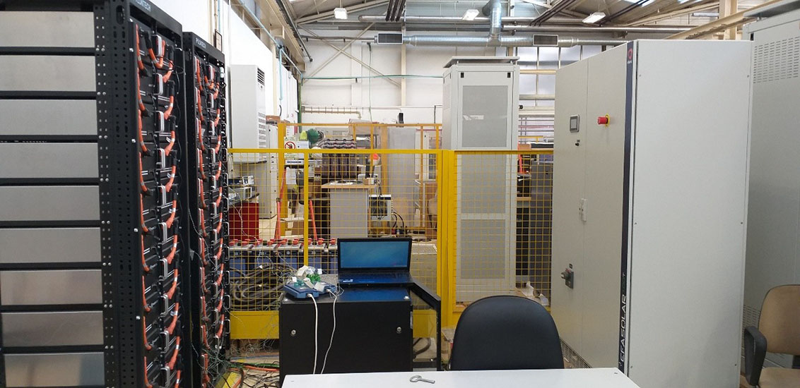
In order to establish the laboratory conditions to perform the unitary tests, as well as the application and integration tests, Efacec installed a 9 m2 battery testing lab – the BatLab – within its power electronic solutions production plant.
The laboratory facilities include the following components:
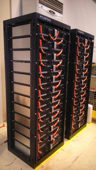
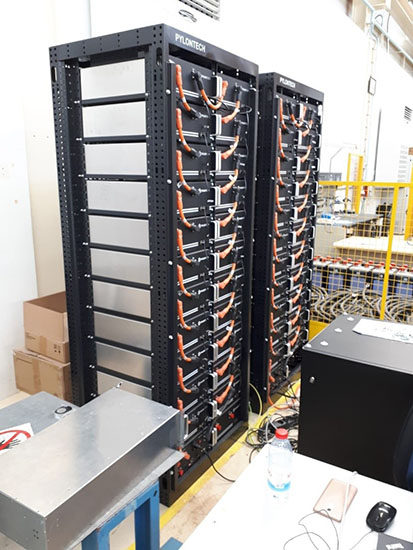
- Two racks of lithium-ion batteries, corresponding to 218 kW / 218 kWh
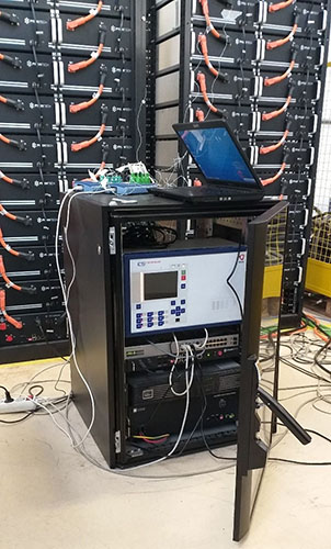
- One small cabinet housing the Master BMS and its specific UPS, the Energy Storage Controller and a LAN switch
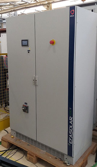
- One 100 kVA battery inverter
- Two DC fuses protecting the DC bus
- The existing testing facilities of the production plant:
- One 40 kW load bank
- One 315 kVA step-up transformer (400 V / 15 kV)
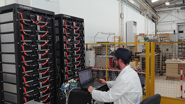
The R&D team has performed the following tests, so far, at the BatLab:
- Integration of the Energy Storage Controller – the ES Controller developed by Efacec within the DEMOCRAT project – with the Master Battery Management System (MBMS) from the battery manufacturer:
- MODBUS protocol integration testing;
- Battery data model validation and database population testing;
- Integration of the Energy Storage Controller with the battery inverter – EFASOLAR Storage – both developed by Efacec:
- MODBUS protocol integration testing
- Inverter data model validation and database population testing;
- Integration of the Energy Storage Controller, the battery system and the inverter connected to the MV grid through a step-up transformer existing in the laboratory facilities:
- Controlled charge and discharge of the batteries;
- Measurement of each battery temperature via each rack’s Battery Management System (BMS), as well as the outside case temperature of selected batteries with sensors, in order to perform the computational flow dynamic study for the thermal behaviour of the battery rack, under different charging and discharging scenarios;
- A set of automation and control applications for energy storage, comprising:
- Active Power Limit;
- Generation/load following;
- Fixed power factor;
- Reactive power injection/absorption;
The following images briefly describe the BatLab components and some of the ongoing tests. |